
Main application
- Slow-running units
- Agitators
- Mixers
Material of Construction
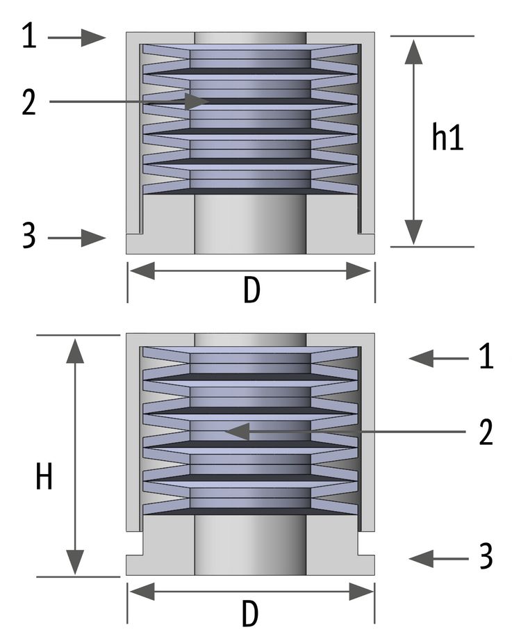
| Part | Material | |
|---|---|---|
| 1 | Springcup | 1.4305 |
| 2 | Spring | 1.8159 galCd |
| 3 | Springcover | 1.4305 |
Note
For best function and long-lasting performance, always use white Antiseize assembly paste to lubricate the threads of the eyeglass bolts.
Installation instructions
The complete packing set is inserted into the stuffing box ring by ring, with the cut ends distributed symmetrically. The uppermost ring should be positioned at least 3 mm below the face of the stuffing box to ensure sufficient guidance for the gland follower. Then use the existing gland nuts to pre-tighten the packing rings in order to minimise further consolidation of the rings.
The nuts and spring columns are then placed on the gland bolts and tightened with the gland nuts. If the bolt length is not sufficient, longer bolts must be used. The nuts must be tightened so that the maintenance gap between part 1 and part 3 closes completely in order to achieve the maximum adjustment force.
The required adjustment force is achieved by turning the gland nut back in 1/6 increments. This opens the maintenance gap.
Functional description
After setting the target value, the gland compression must be adjusted to the leakage. The width of the maintenance gap can be used as a guide.
PROLOAD-DYN LiveLoading
New generation LiveLoading with encapsulated disc spring system and defined compression length for slow-moving shafts.
Characteristics
- One of the main advantages of the PROLAOD-DYN LiveLoading system is that the disc springs slide on a smooth surface and cannot cannot catch on thread turns
- The spring packs are protected in a housing against environmental influences and damage.
- The spring stack is adjusted for optimal spring force and spring deflection by a spacer sleeve and a defined maintenance gap.
- A torque wrench is not required for adjustment.
- A reduction in compression due to packing consolidation or volume loss through abrasion is indicated by a larger maintenance gap. In this case, simply tighten the gland nut to restore the desired compression.
Dimensions
| Setting force | Tightening torque | ||||||
| Unclamped height(H) | Height of closed maintenance gap (h1) | Diameter (D) | Min | Max | Min | Max | |
| (mm) | (mm) | (mm) | (N) | (N) | (Nm) | (Nm) | |
| R10 | 35 | 32 | 25 | 375 | 883 | 0.9 | 1.8 |
| R10HI | 35 | 32 | 25 | 560 | 2560 | 1.5 | 5.1 |
| R12 | 43 | 37 | 30 | 661 | 1359 | 1.2 | 3.3 |
| R12HI | 43 | 37 | 30 | 1425 | 2926 | 2.5 | 6.9 |
| R12XT | 42 | 37 | 30 | 2778 | 5705 | 4.9 | 13.5 |
| R14 | 47 | 40.5 | 36 | 1176 | 2597 | 2.3 | 7.2 |
| R14HI | 47 | 40.5 | 36 | 2796 | 6173 | 5.4 | 17.1 |
| R16 | 47 | 40.5 | 36 | 1176 | 2597 | 2.5 | 7.8 |
| R16HI | 47 | 40.5 | 36 | 2796 | 6173 | 5.9 | 18.6 |
| R20 | 51 | 44 | 45 | 1871 | 5701 | 6.1 | 22.2 |
| R20HI | 51 | 44 | 45 | 2975 | 8965 | 9.6 | 34.9 |
Dimension
| Setting force | Tightening torque | ||||||
| Unclamped height(H) | Height of closed maintenance gap (h1) | Diameter (D) | Min | Max | Min | Max | |
| (inch) | (inch) | (inch) | (lbf) | (lbf) | (ftlb) | (ftlb) | |
| R3/8 | 1.38 | 1.26 | 0.98 | 68 | 198 | 0.4 | 1.3 |
| R3/8HI | 1.38 | 1.26 | 0.98 | 101 | 575 | 1.0 | 3.8 |
| R7/16 | 1.69 | 1.46 | 1.18 | 148 | 305 | 0.8 | 2.3 |
| R7/16HI | 1.69 | 1.46 | 1.18 | 309 | 657 | 1.8 | 5.0 |
| R1/2 | 1.77 | 1.50 | 1.34 | 143 | 305 | 0.7 | 2.6 |
| R1/2HI | 1.77 | 1.50 | 1.34 | 319 | 639 | 1.5 | 5.4 |
| R9/16 | 1.85 | 1.59 | 1.42 | 248 | 583 | 1.7 | 5.5 |
| R9/16HI | 1.85 | 1.59 | 1.42 | 585 | 1387 | 4.1 | 13.0 |
| R5/8 | 1.85 | 1.59 | 1.42 | 215 | 583 | 1.9 | 6.0 |
| R5/8HI | 1.85 | 1.59 | 1.42 | 512 | 1387 | 4.5 | 14.2 |
| R3/4 | 2.01 | 1.73 | 1.77 | 411 | 1281 | 4.4 | 16.1 |
| R3/4HI | 2.01 | 1.73 | 1.77 | 649 | 2015 | 6.9 | 25.3 |